Skip to the content
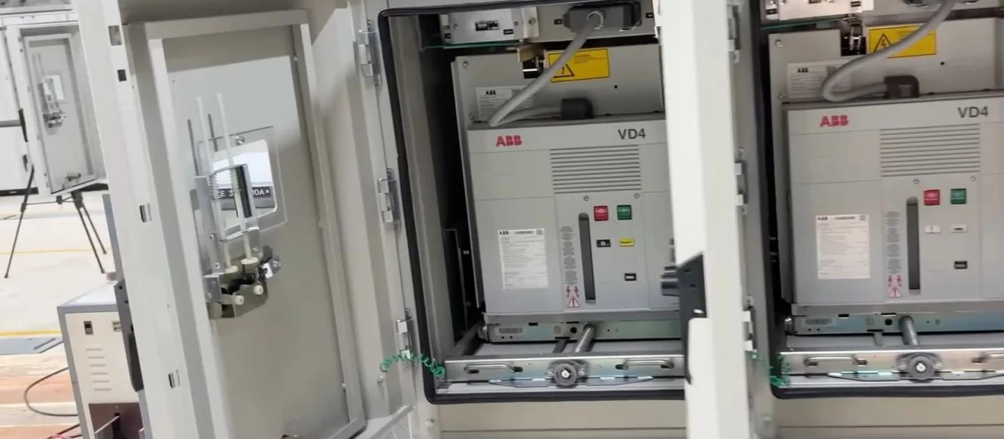
Vacuum circuit breakers in the open panels of a medium-voltage switchboard

Medium Voltage

Medium-voltage substations, from the utility's intake to the transformers that feed the building.

We design, supply, install, test and commission the medium-voltage systems of buildings and campuses, and maintain the systems we installed. A system takes the utility's supply, at 11 kV in most of the UAE and at the voltage of the local network elsewhere, from 6.6 to 33 kV, through the intake switchgear and the ring main units to the transformers that step it down to 400 V, with the protection, the control supplies, the cables and the earthing of each substation.

The design starts from the loads and from the supply the utility offers: the maximum demand of the building, the number of feeders, and the fault level at the point of connection. A hospital or a data centre takes two feeders from separate sources where the network allows it. We calculate the short-circuit currents to IEC 60909, rate the switchgear and the cables for them, grade the protection so that a fault is cleared by the device nearest to it, and study the arc flash energy to IEEE 1584; the substation itself we design to IEC 62271-200, IEC 61936-1 and the utility's own regulations.

We supply the switchgear, the ring main units, the transformers and the protection relays from the brands we carry, and our teams install, terminate and test them on site. Before energisation each cable is tested for its insulation and its withstand voltage, each relay by secondary injection and each transformer for its ratio, vector group and insulation, and the substation is energised with the utility. Under a service contract we then maintain the systems we installed: switchgear inspected and operated, relays retested, transformers surveyed by thermography and, where they are oil-immersed, their oil analysed.

Switchgear, ring main units and protection

Where a building connects to a utility ring, we design its substation around ring main units: two load break switches on the ring, rated 630 A, and a vacuum circuit breaker or a fuse switch for each transformer. Larger intakes take metal-enclosed switchgear to IEC 62271-200, with withdrawable vacuum circuit breakers, a rated short-time withstand current of 20 or 25 kA for 3 s to suit the network, loss of service continuity category LSC2 and internal arc classification IAC AFLR, so that an arc inside a panel is vented away from anyone in front of it, beside it or behind it.

Each feeder has numerical relays for overcurrent and earth fault protection, with differential protection on large transformers and cables, and trips through a lockout relay that must be reset by hand before the feeder can close again. The relays, the tripping and the closing run on a 110 V DC supply from a battery with duty and standby chargers, and report over IEC 61850 to the substation's control system and to the building management system.

Transformers, cables and substations

Indoors we design with cast resin transformers to IEC 60076-11, of climatic class C2, environmental class E2 and fire behaviour class F1, which resist burning and need no oil pit; outdoors and for large ratings, oil-immersed transformers with natural cooling stand in bunds that hold their oil. A typical building transformer is 11/0.4 kV, 1000 to 2500 kVA, vector group Dyn11 with an impedance of 6 per cent, rated for the 50 °C ambient of a Gulf summer, with winding temperature sensors that first raise an alarm and then trip.

The cables are copper or aluminium with XLPE insulation to IEC 60502-2, sized for the fault current as well as the load and the way they are laid. We lay out each substation for safe operation and replacement, with its clearances, cable trenches, the ventilation that carries the transformers' losses away and its fire separation, and design its earthing so that the touch and step voltages of an earth fault stay within the limits of IEC 61936-1 and IEEE 80.

Systems and equipment

Switchgear

  • Ring main units: gas-insulated, with load break switches on the ring and a circuit breaker or fuse switch for each transformer
  • Metal-enclosed switchgear: withdrawable vacuum circuit breakers, internal arc classified, for intakes and large distribution
  • Metering panels: the utility's tariff metering with its current and voltage transformers
  • Earthing switches and interlocks: so that the safe sequence of operation is the only one possible

Protection and control

  • Numerical protection relays: overcurrent, earth fault and differential protection, with fault records
  • Lockout relays and control switches: hand-reset tripping and local control at each panel
  • Auxiliary DC supplies: 110 V batteries with duty and standby chargers
  • Substation control: IEC 61850 or Modbus links to the control system and the building management system

Transformers

  • Cast resin transformers: dry-type, of classes C2, E2 and F1, for indoor substations
  • Oil-immersed transformers: naturally cooled, hermetically sealed or with a conservator, in bunds outdoors
  • Transformer protection: winding temperature relays, and gas and pressure relays on oil-immersed units
  • Package substations: the switchgear, the transformer and the low-voltage board in one enclosure, for outdoor sites

Cables and earthing

  • Medium-voltage cables: XLPE-insulated, copper or aluminium, sized for load, fault and installation
  • Terminations and joints: heat-shrink or cold-shrink, indoor and outdoor
  • Substation earthing: grids and electrodes designed for the touch and step voltages of an earth fault
  • Cable tests: insulation resistance and very low frequency withstand tests before energisation

Standards we work to

  • IEC 62271-200: AC metal-enclosed switchgear and controlgear above 1 kV and up to 52 kV
  • IEC 62271-100: high-voltage alternating current circuit-breakers
  • IEC 60076: power transformers, with part 11 for dry-type transformers
  • IEC 60502-2: power cables with extruded insulation from 6 kV up to 30 kV
  • IEC 61936-1: power installations exceeding 1 kV AC
  • IEC 60909: short-circuit currents in three-phase AC systems
  • IEEE 1584: arc-flash hazard calculations
  • The regulations of the UAE's electricity authorities, those of DEWA in Dubai among them